Partial Discharge
Background
Partial Discharge (PD) activity is an electrical discharge, which does not bridge the electrodes between an insulation system completely under high electric field stress, causing dielectric breakdown. It can be found at any point of an insulation system, where the electric field strength is over the breakdown strength of the insulation material. It occurs as symptoms of a number of failure mechanisms related HV system. By adopting PD measurement, PD activity can be detected in advance, and further prevent operational failure or even more serious consequences from occurring.
Figure 1. Electric tree found in insulation system
Partial Discharge Measurement
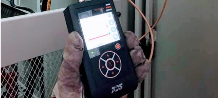
Up to now, PD measurement is considered as the most effective diagnostic to prevent electrical failure. Along with the existence of PD, there are various phenomenon, such as light, heat, sound, chemical byproducts and electromagnetic transients are all detectable by proper methods. In this proposal, we will deliver UHF method (Fig. 2a) by means of magnetic coupling, and acoustic (Fig. 2b) as a supplement method. Both techniques are according to IEC 62478 – Measurement of Partial Discharge by Electromagnetic and Acoustic Methods, which standardizes the methods for on-line testing.

Figure 3. Partial Discharge measurement methods
PD measuring method of magnetic field coupling
Cable termination is one example to explain the on-line PD measurement theory. Whenever a PD activity occurring inside the cable termination, PD pulse signal will flow throughout the cable in wave-form. From equation below, we know that transient current IE(t) will lead to change in transient voltage UE(t).UE(t)= IE(t)*Zw
where UE(t) is transient voltage
IE(t) is transient current
Zw is cable resistance
The transferring of pulse current IE(t) of partial discharge between wire and ground wire will result magnetic field. At this point, inductor sensor, such as UHF CT and Rogowski coil can be used to measure the magnetic line of flux caused by transient current, and this is the principle of magnetic coupling (Fig. 4)

Fig. 4. Magnetic coupling equivalent circuit
According to PD measurement theory, PD signal can be measured by ground cable of cable termination. High Frequency CT (HFCT) is one common type of sensor for magnetic field measurement, but the bandwidth of HFCT is usually under 20 MHz where the noise plays a huge factor; therefore, S/N ratio extracted from on-line measurement within this bandwidth will be considerably low. Under certain range of bandwidth, PD signal will be difficult to measure due to oversized noise. In this article, we will discuss about how Ultra High Frequency sensor can improve the S/N ratio, in order to enhance the effectiveness of measurement. The principle of how UHF sensor and magnetic coupling work the same, which measures the magnetic change of pulse current.

Fig. 5. UHF sensor measuring principle
The Advantage of UHF Method
Cable system shares similar characteristic as antenna, which receives much noise from the background, especially for HF sensors. HF-CT is most used for on-line PD measurement on cables, but the HF-CT measuring frequency is limited below 50MHz, which results a very low signal to noise ratio, so PD pulses in the pC range may not be detected.


Figure 6. Indication of the relationship between noise and frequency
In the comparison, we installed both UHF and HF sensors on the same equipment, and inject signal with a calibrator, to compare and analyze the outcome. As a result, HF-CT
shows a much higher background noise by waveform and spectrum analysis.
")
Figure 7. Comparing UHF CT and HFCT by installing both on the same equipment

Figure 8. Background noise by waveform

Figure 9. Background noise by spectrum

Figure 10. Test result of 500pC injection