Damped AC Testing
Background
Power cable is considered as a capacitive equipment. While utilizing AC power source for high voltage testing, the size of power supply would be huge and is difficult to move. In this circumstance, AC resonant testing system is often used as a substitution, even though the related equipment is still quite bulky.On the other hand, if DC power is applied, the only difficulty is the charging current of the cable system, and the size of power supply is small to carry. However, a few notable disadvantages of utilizing DC power in XLPE cable testing are: different electrical field distribution between AC and DC, space charge, can’t discover the defects, facilitating the development of water tree into electrical tree and etc.
Currently there are two alternatives: Very Low Frequency (VLF)
and Damped Alternating Current (DAC).
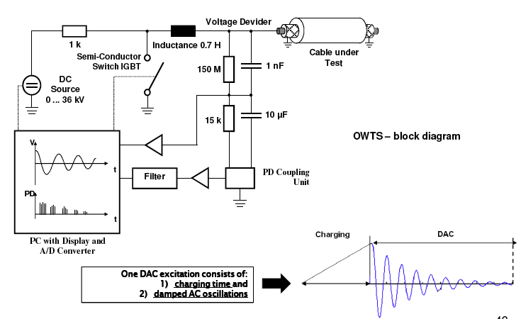
The test structure of DAC is shown in figure 1.

TEST methodology
Partial Discharge Measurement
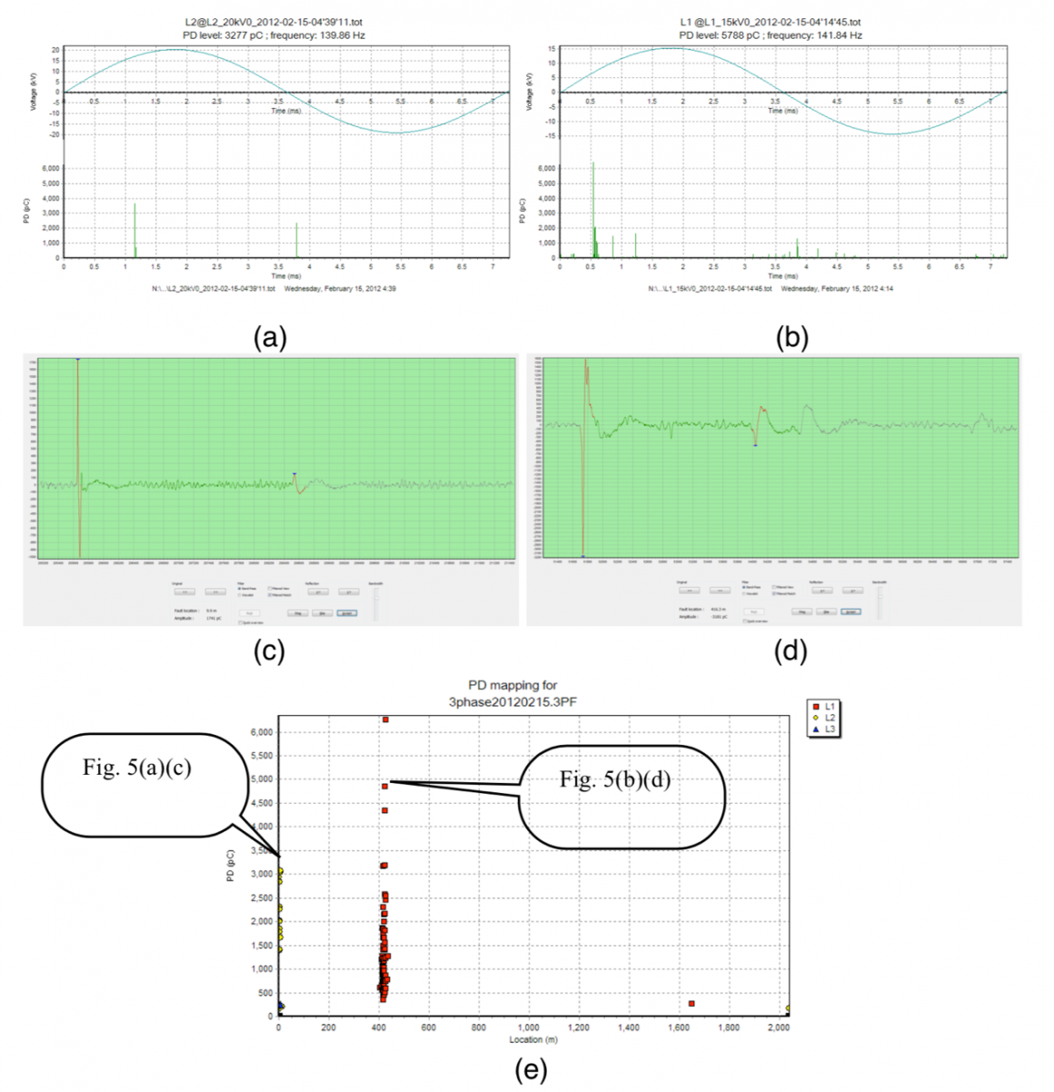
Partial Discharge (PD) Measurement utilizing DAC system is in accordance with IEC 60270 standard testing. As shown in figure 1, the test system has a built-in coupling capacitor; based on the test item, the filter is programmed differently: one is standard testing where frequency is < 500 kHz, and another is PD measurement where frequency is between 150 kHz and 45 MHz.During PD measurement, standard testing method is applied (500 kHz LPF). The measurement instrument will record the voltage waveform and PD waveform, which are used to determine the existence of PD phenomenon. Figure 2 and 3 demonstrate the waveform without and with PD signal respectively. In figure 2, there is no abnormal pulse signal at each voltage cycle, meaning no PD activity. In figure 3, there are pulse signal appearing at specific quadrant in the voltage cycle, showing the evidence of PD activities, which would require further analysis on pulse waveform to determine the signal source.


Waveform without / with PD
Partial Discharge Location
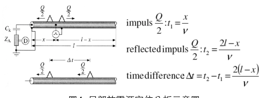
Figure 4 is a schematic diagram of PD location, where the total length of cable is I meter, and PD source is located x meter away from the test end; △t is the time difference of two signals observed, and PD signal is traveling at a velocity at v m/ms.
Figure 4. PD Location Analysis
Figure 5(a)(b) are the PD measurement result, indicating the evidence of pulse signal, and figure 5(c)(d) are the expanded waveform of 5(a)(b). Figure 5(e) is the analysis result based on previous calculation.
Figure 5(a) is the surface discharge on cable termination.
Figure 5(b) is the partial discharge found in cable joint.

Figure 5. PD Location result
FAQs
-
Q1. Does DAC testing stresses insulation with DC stresses?
No.
According to the fundamentals of electric fields the DAC testing is using damped AC voltages and as such it stresses the insulation with AC voltages only. -
Q2. Does DAC have well defined test parameters?
Yes.
The DAC test voltage is given by the [7, 8] and the maximum DAC withstand voltage level is determined by the voltage peak values VDAC respectively RMS-values VDAC/√2 of the 1st DAC cycle. By applying DAC withstand test the cable section can be stressed with a selected DAC voltage stress for selected time duration and the cable section can be rejected when a breakdown has occurred. Moreover, for strong inhomogeneous insulation defects (which have PD occurrence) DAC stresses are less destructive as continuous AC stresses. Which means, that the microscopic breakdown-channel examination might deliver some more information about the reason of the breakdown. The DAC parameters are well defined. According to [1, 2, 3] the DAC withstand test duration is given by 50 DAC excitations. Despite the fact that AC testing needs up to 1 hour over-voltage test application, the application of 50 DAC excitations has been demonstrated to be representative to obtain in case of investigated defects the breakdown. -
Q3. May space charge developments occur during DAC testing?
No.
The continuous increasing voltage in the energizing phase results in an AC field distribution without DC stresses. Furthermore there is no steady-state DC condition reached due to the continuous uni-polar voltage increase. The relative short duration of the energizing phase (tens of seconds) in combination with the applied electrical field (< 20 kV/mm) there is no space charge accumulation in the cable insulation. As the switching is immediately followed after reaching the selected test voltage, there is no steady state condition reached at all. After the switching the damped AC period represents a bipolar AC discharging process after which no remaining charges are present. -
Q4. Is DAC testing dangerous to the cable insulation?
No.
Faultless insulation never will be harmed by DAC testing. But in contrast to continuous non-monitored AC testing with over-voltages up to 2Uo the DAC testing is always monitored by PD detection. In the case of strong- inhomogeneous defects in the insulation, the sensitive PD measurement detects this occurrence of PD and is used to control the insulation degradation process. Thus, a positive DAC test result not only gives certainty about the passed withstand test additionally it shows a non PD-deteriorated insulation, ready for reliable service. -
Q5. Is the AC electrical field distribution during DAC energizing?
Yes.
During the energizing phase a continuously increasing uni-polair voltage is applied to the cable. During this time a capacitive AC field distribution is present only. While the energizing is continuous and directly followed by the damped AC phase when the voltage is reached, no steady state (DC) condition will occur. The continuous increasing voltage in the energizing phase results in an AC field distribution without DC stresses. So DAC withstand testing provides an ongoing continues AC stress for the duration of the withstand test. -
Q6. Can DAC testing be used for after-laying testing of new cables?
Yes.
Similar to AC testing 20Hz up to 300Hz 1hour, or 24 hours Uo, also the DAC testing is one of the alternative methods to test new-installed power cables up to 350kV. -
Q7. Can DAC testing be used for maintenance and diagnostic testing of repaired and service aged cables?
Yes.
Using monitored DAC testing for maintenance purposes provides sensitive way of checking the installation quality of the repaired site by applying DAC withstand test and by performing standardized PD detection.
In case of service aged cable circuits the combination of PD detection and dissipation factor estimation is a very powerful tool for condition assessment of aged XLPE and Oil-impregnated insulation. -
Q8. Does DAC testing allow performing sensitively standardized PD detection on-site?
Yes.
In contrast to typical mobile AC system with very high level (up to 1.000pC) of electromagnetic disturbances the DAC systems are characterized by very low PD background level (below 5pC) and the ability of IEC 60270 standardized PD detection. -
Q9. Is the use of DAC testing standardized?
Yes.
Damped AC voltage is in the range of 20Hz up to 300Hz and is a sinusoidal AC voltage and as mentioned in and as such is recommended test voltages for on-site testing:
● IEC 60840: Power cables with extruded insulation and the accessories for rated voltages above 30kV up to 150kV Test methods and requirements;
● IEC 62067: Power cables with extruded insulation and the accessories for rated voltages above 150kV; Furthermore standards which are applicable for on-site testing with damped AC are:
● IEC 60060-3: High Voltage test techniques Part 3: Definitions and requirements for on-site testing;
● IEEE 400: Guide for Field Testing and Evaluation of the Insulation of Shielded Power Cable Systems Rated 5 kV and Above;
● HD 632 S2 (CENELEC): Power cables with extruded insulation and their accessories for rated voltages above 36kV (Um=42kV) up to 150kV (Um= 170kV)
● IEEE 400.4: Guide for Field-Testing of Shielded Power Cable Systems Rated 5 kV and above with Damped Alternating Current Voltage (DAC) (draft under preparation) -
Q10. Is the use of damped AC testing better than the use of conventional continuous AC testing?
Yes.
Referring to table 1 and 2 it is obvious that the DAC technology represents most modern way of on-site testing and diagnosis of power cable networks. Many power utilities, manufacturers and service providers’ around the world are using successfully this technology. In medium voltage area this test voltage type is very successfully applied for over 10 years. Very good experiences and results in HV and EHV cable testing are gathered since 5 years. Information about scientific results, practical cases and technology descriptions are published in more than 100 technical and scientific publications and books.
